
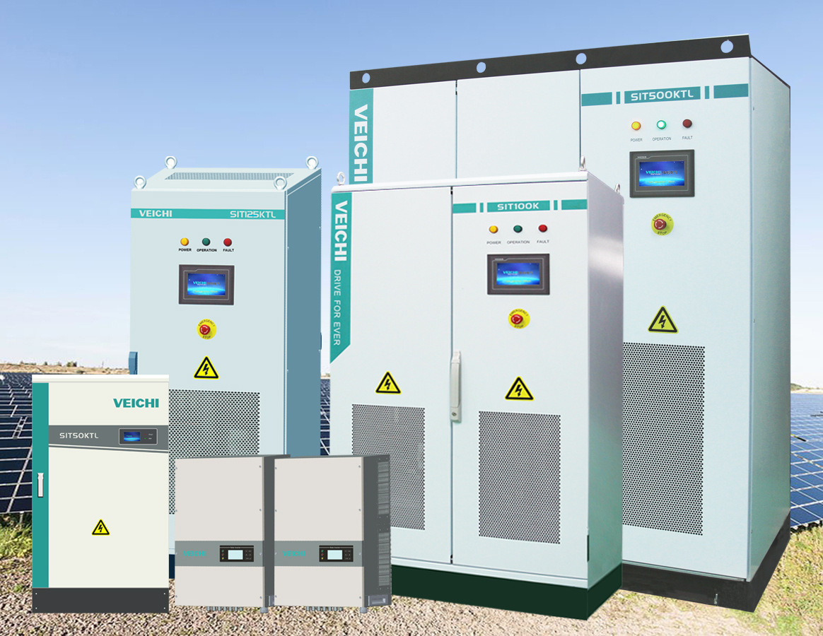
What is a photovoltaic inverter
Inverter, also known as power regulator, can be divided into independent power supply and grid-connected use according to the use of inverter in photovoltaic power generation system. According to the waveform modulation method, it can be divided into square wave inverter, step wave inverter, sine wave inverter and combined three-phase inverter. For inverters used in grid-connected systems, it can be divided into transformer-type inverters and non-transformer-type inverters according to whether there is a transformer.
Structural Principles
The inverter is a power adjustment device composed of semiconductor devices, which is mainly used to convert DC power.
Convert to AC power. It is generally composed of a boost circuit and an inverter bridge circuit. The boost circuit boosts the DC voltage of the solar cell to the DC voltage required for inverter output control; the inverter bridge circuit converts the boosted DC voltage into an AC voltage with a common frequency equivalently. The inverter is mainly composed of switching elements such as transistors. By regularly turning the switching elements on and off (ON-OFF), the DC input is turned into an AC output. Of course, such an inverter output waveform simply generated by opening and closing the loop is not practical. Generally, it is necessary to use high-frequency pulse width modulation (SPWM) to narrow the voltage width near the two ends of the sine wave and widen the voltage width in the center of the sine wave, and always make the switching element move in one direction at a certain frequency during the half cycle, thus forming A pulse train (quasi-sine wave). Then let the pulse wave pass through a simple filter to form a sine wave.
The composition of components:
1. Current sensor
Photovoltaic inverters generally use Hall current sensors for current sampling. The current sensors used vary from low power to high power. Some examples are as follows:Outline drawing of JCE1005-FS current sensor in 500KW inverter
Outline drawing of JCE1005-FS current sensor in 500KW inverter
100KW: The detection current is about 300A, and the JCE308-TS7 current sensor is generally used
250KW: The detection current is about 500A, and the JCE508-TS6 current sensor is generally used
500KW: The detection current is about 1000A, and the JCE1005-FS current sensor is generally used
1MW: The detection current is about 2000A, and the JCE2005-FS current sensor is generally used
For current sensors that require high accuracy, fast response time, and environmental requirements such as low temperature and high temperature resistance, many domestic manufacturers use open-loop current sensors to replace closed-loop current sensors, such as: JCE1000-AXS, JCE1500-AXS, JCE2000-AXS, etc.
2. Current transformer
BRS series current transformers are generally used, ranging from hundreds to thousands of A, and the output signal is generally 0-5A as the standard
3. Reactor
Function
The inverter not only has the function of DC-AC conversion, but also has the function of maximizing the performance of the solar cell and the function of system fault protection. To sum up, there are automatic operation and shutdown functions, maximum power tracking control function, anti-independent operation function (for grid-connected system), automatic voltage adjustment function (for grid-connected system), DC detection function (for grid-connected system), DC grounding detection Function (for grid-connected systems). Here is a brief introduction to the automatic operation and shutdown functions and the maximum power tracking control function.
1. Automatic operation and stop function
After sunrise in the morning, the intensity of solar radiation increases gradually, and the output of the solar cell also increases. When the output power required by the inverter is reached, the inverter starts to run automatically. After entering into operation, the inverter will monitor the output of the solar cell module all the time. As long as the output power of the solar cell module is greater than the output power required for the inverter to work, the inverter will continue to run; it will stop at sunset, even if it is cloudy and rainy. The inverter can also operate. When the output of the solar cell module becomes smaller and the output of the inverter is close to 0, the inverter will form a standby state.
2. Maximum power tracking control function
The output of a solar cell module varies with the intensity of solar radiation and the temperature of the solar cell module itself (chip temperature). In addition, since the solar cell module has the characteristic that the voltage decreases with the increase of the current, there is an optimum operating point where the maximum power can be obtained. The intensity of solar radiation is changing, and obviously the optimal working point is also changing. Relative to these changes, the operating point of the solar cell module is always at the maximum power point, and the system always obtains the maximum power output from the solar cell module. This control is the maximum power tracking control. The biggest feature of inverters for solar power systems is that they include the function of maximum power point tracking (MPPT).
Shopping elements
Energy saving and environmental protection are the focus of everyone’s attention. The photovoltaic industry has become a popular industry from Europe, Australia, and now China. In just a few years, domestic photovoltaic inverter manufacturers have sprung up, but how to choose a solar inverter This is still a certain standard.
The inverter is a key component in the solar photovoltaic power generation system, so it has high requirements for the inverter. When selecting an inverter, attention should be paid to whether its technical specifications meet the requirements of the system design. Generally focus on the following technical indicators.
Purchase steps and methods
1. PowerGenerally, the inverter corresponding to the power segment is configured according to the requirements of the system. The power of the selected inverter should match the maximum power of the solar cell array. Generally, the rated output power of the photovoltaic inverter is selected to be close to the total input power. This saves costs.
2. Key technical indicators
1) Select the appropriate input and output voltage range to ensure the optimal combination of products.
2) The European efficiency of the inverter: its level will directly affect the design cost and power generation efficiency of the photovoltaic power generation system.
3) Solar cell array maximum power tracking function (MPPT) and its efficiency.
4) It should be noted that the selected inverter should have basic protection functions, such as overcurrent/short circuit protection, overpower protection, overtemperature protection, lightning protection, island protection and other functions.
5) The inverter output current waveform distortion rate (THD%) should be lower than 4%.
3. Certification standards
As the core equipment of a photovoltaic power station, in order to ensure the stable, reliable and continuous operation of the power station, the grid-connected inverter must have high reliability. It should have the safety certification of the sales destination, the electromagnetic compatibility certification, and the grid connection certification of various countries: (take Europe as an example)
Safety regulations: EN62109-1, EN62109-2
Electromagnetic compatibility: EN61000-6-1, EN61000-6-2, EN61000-6-3, EN61000-6-4
Grid-connected certification: VDE0126-1-1 (Germany)
4. Brand and service
It is recommended to buy a brand with a good reputation in the current market, because generally a company with a good brand image usually has a large investment in technology and maintenance services, which can meet the commitment to customers.
working environment
1. Photovoltaic inverters require high efficiency. Due to the high price of solar cells in 2011, in order to maximize the use of solar cells and improve system efficiency, we must try to improve the efficiency of the inverter.
2. Photovoltaic inverters require high reliability. In 2012, the photovoltaic power generation system was mainly used in remote areas, and many power stations were unattended and maintained. This requires the inverter to have a reasonable circuit structure, strict component selection, and requires the inverter to have various protection functions, such as input DC polarity reverse protection, AC output short circuit protection, overheating, overload protection, etc.
3. The photovoltaic inverter requires a wide range of DC input voltage. Since the terminal voltage of the solar cell changes with the load and the intensity of sunlight, although the battery plays an important role in the voltage of the solar cell, the voltage of the battery varies with the remaining voltage of the battery. The change of capacity and internal resistance fluctuates, especially when the battery is aging, its terminal voltage has a large range of change, such as a 12V battery, its terminal voltage can vary between 10V and 16V, which requires the inverter to be larger. The normal operation is guaranteed within the range of the DC input voltage, and the stability of the AC output voltage is guaranteed.
4. Photovoltaic inverter In medium and large-capacity photovoltaic power generation systems, the output of the inverter power supply should be a sine wave with less distortion. This is because in medium and large-capacity systems, if a square wave is used for power supply, the output will contain more harmonic components, and higher harmonics will generate additional losses. Many photovoltaic power generation systems are loaded with communication or instrumentation equipment. The equipment has high requirements on the quality of the power grid. When the medium and large-capacity photovoltaic power generation systems are connected to the grid, in order to avoid power pollution with the public power grid, the inverter is also required to output sine wave current.